Author: Paul B. Anders ( pbanders@gmail.com
)
Date: 01/15/2026
Version: 2.6
PLEASE NOTE - I am not in the business of calibrating or repairing MPS's. I provide the pages here to assist others in learning how to do these procedures to avoid paying the outlandish prices (e.g. $1100) for new MPS's and to assure that the rebuilt unit you bought is actually adjusted correctly for your application. I will be glad to consult with you by email if you have any questions or need help.
NEW: This (v2.2 and beyond) is an extensive revision and simplification of the previous versions of this page, with corrections to some errors in the understanding of the operation of the MPS. As of v2.4, I have removed and cleaned up obsolete links.
The manifold pressure sensor (MPS) is an interesting and complex electromechanical device. The MPS is the most important sensor in the D-Jetronic system. The MPS measures engine load by sensing manifold pressure, transforming the load signal into an electrical response that the ECU uses to determine the appropriate injector pulse duration. Unlike modern fuel injection systems with oxygen sensors, D-Jetronic is an "open loop" system, meaning that the ECU has no feedback that the pulse duration used produced the correct mixture. Without feedback, the ECU cannot compensate for mixture changes required by engine modification (e.g. larger displacement, intake modifications, turbocharging, etc.), engine wear, or fuel composition. While time has shown that the D-Jetronic system does an amazingly good job in spite of this limitation, corrections to the mixture may be required, and an adjustment and calibration method for the MPS is desired.
The purpose of this document is to analyze the MPS in detail and to describe a calibration and adjustment procedure.
I've reviewed and revised this document to attempt to improve clarity with regard to pressure and vacuum. "Positive" pressure means pressures above the local atmospheric pressure (which varies with altitude and weather). "Reference" pressure is the pressure at sea level, which is 760 torr. "Vacuum" is the same as "Negative" pressure, the pressure below local atmospheric pressure. "Increasing vacuum" means the same as "decreasing pressure", and vice versa. While it would be desirable to speak only of pressure, most of the actual measurements of chamber pressures, such as the intake manifold, are measured using vacuum gauges, so both vacuum and pressure are used where appropriate in this document. I would appreciate an email if discrepancies are noted.
To understand the MPS operation, the fuel requirements of a loaded engine must be understood. A good source is the book "Bosch Fuel Injection and Engine Management" by Charles O. Probst. I recommend reading chapters 2 and 3 to develop a good working knowledge. I will only be discussing how the MPS responds to engine load here, and will not go into the many details that are covered in the Probst book. A review of my web page on the fundamentals of the D-Jetronic injection system may be helpful.
The MPS measures engine load by sensing the manifold pressure. In modern FI systems based on manifold pressure, pressure measurement is performed by inexpensive, simple, and reliable solid-state sensors. At the time of the development of the D-Jetronic system (mid-1960's), such sensors were nearly 30 years in the future. Precision electrical pressure sensors of the time were based on Linear Variable Transformer (LVT). The LVT used in the MPS is a very reliable device - failures of the MPS are generally due to mechanical failures of the aneroid cells and diaphragm in the unit, due to metal fatigue. LVT's offer essentially infinite resolution, fast linear response, and resistance to harsh environments. Today's solid state sensors offer most of the same advantages, and are tougher and simpler to interface.
The standard method used with an LVT for displacement measurements is to apply a reference sine wave to the input and measure the amplitude of the output sine wave, which varies linearly with displacement across most of the range of the device. Bosch , however, did not use this standard method. Instead, a pressure-sensing loop circuit directs a current through the primary coil which decays at a rate dependent on the armature position, and correspondingly, the manifold pressure. The induced current in the secondary holds the output of the circuit on until the current decays below a threshold value, generating the basic injection pulse. See my ECU page for details. This method saved Bosch a considerable amount of circuitry, an important design consideration in the mid-1960's. For our understanding, this distinction is unimportant, as the effect used is still linear with displacement of the LVT armature.
For the purposes of the following discussion, the engine is assumed to be at operating temperature, no vacuum leaks present, and the auxillary air valve is closed and the PCV operating properly.
At idle, the manifold vacuum is about 10 to 14 in. Hg (inches of mercury (Hg), a common unit used for vacuum). Note that the actual idle vacuum level will vary somewhat with the wear level of the engine. At part-load the vacuum is between the idle level and about 6 in. Hg. The transition to full-load operation begins at about 6 in. Hg, completing by about 2 in. Hg. The MPS is designed to respond to two fundamental load conditions, part-load and full-load. Idle mixture is controlled by a special circuit in the ECU that senses the idle condition from the throttle position sensor (TPS). Part-load operation requires a linear response to load, and the mixture is a compromise between performance, fuel economy, and emissions. Full-load enrichment requires a quick transition from the part load response for increased enrichment to provide maximum power output, as the manifold pressure increases to near atmospheric pressure.
Given the discussion above, the MPS response curve appears as follows:
To produce the response shown in the diagram above, the MPS needs to have both part-load and full-load modes of operation. A pair of aneroid cells coupled to the LVT provides part-load operation, and a separate diaphragm coupled to the aneroid cells provides full-load operation. We will analyze the MPS operation in three conditions: idle, part-load, and full-load.
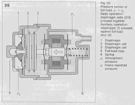
Below is a diagram of the MPS under idle conditions:
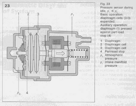
The LVT, aneroid cells (2 and 3 in the diagram), and full-load diaphragm (1) are visible in the diagram. At idle, the MPS chamber pressure (p1) is coupled to the intake manifold, at a lower pressure (approximately 14 in. Hg) than the full-load chamber (p0) which is open to atmospheric pressure through a small vent in the MPS case. The pressure differential across the diaphragm overcomes the force from the spring (in the RH end of the case) and causes the full-load diaphragm to be pressed against the part-load stop (4). The aneroid cells are evacuated during manufacturing (as per the Scholl patent). Under the low pressure in the MPS chamber at idle, the aneroid cells expand. As a result, the armature is driven out of the core (the arrow to the right), reducing the inductive coupling between the coils. The contact trigger pulse is thereby minimally coupled to the output coil, causing the ECU to develop a shorter injection pulse. However, at idle, the throttle position sensor turns on the idle circuit in the ECU, which lengthens the pulse and enriches the mixture independently of the MPS response.
Below is a diagram of the MPS under part-load conditions:
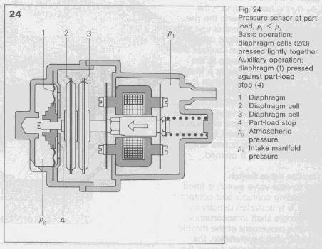
Part-load operation covers manifold pressures from idle levels to the full-load transition pressure (p', about 6 in. Hg). In this mode of operation, the diaphragm is still pressed against the part-load stop, due to the pressure differential between the two chambers, and the movement of the armature is directly coupled to the compression of the aneroid cells. As engine load increases the manifold pressure decreases, causing the anaeroid cells to compress and pull the armature into the LVT coil (the arrow to the left), increasing the inductive coupling and lengthening the basic injection pulse duration.
Below is a diagram of the full-load diaphragm assembly:
Please excuse my poor drawing skills, but the small "^" about half-way across the diameter of the diaphragm is a pleat. In a real MPS diaphragm, there three such pleats, enabling movement of the center of the diaphragm when pressure is applied and the pleats unfold.
The inner screw acts directly on the aneroid cells and adjusts the part-load mixture. The action of the outer screw will be discussed below in the adjustments section .
Below is a diagram of the MPS under full-load conditions:
As the load increases, the intake manifold pressure approaches atmospheric pressure. At the transition pressure p', the force from the coil spring (6) exceeds the pressure differential force on the diaphragm, and the diaphragm begins to move away from the part-load stop. This movement proceeds quickly, with a larger movement per unit pressure compared to the response of the aneroid cells, increasing the inductive coupling between the coils. The ECU increases the basic injector pulse width to a maximum, providing full-load enrichment. The full-load stop sets the maximum amount of movement, and therefore, enrichment. The intake manifold pressure where the diaphragm is activated (p') is determined by the spring constant of the coil spring. From reference 1, the transition pressure p' was targeted at about 100 Torr below atmospheric pressure (about 6 in. Hg), and the full-load stop engagement pressure was set to 50 Torr below atmospheric pressure (about 2 in. Hg). The outer screw adjustment changes the extent of the transition by limiting the throw the diaphragm.
The MPS on early D-Jetronic cars lacked the full-load diaphragm. Instead, full-load was sensed by a pressure switch on the intake manifold that turned on when the manifold pressure was 700 Torr, about 60 Torr below the sea level atmospheric pressure. The switch signaled the ECU to enrich the mixture for maximum power, to approximately a 12.7:1 air/fuel ratio. The switch caused an abrupt transition between part-load and full-load, which resulted in drivability problems. Additionally, the engagement of full-load was dependent on the absolute atmospheric pressure. At high altitudes, where the atmospheric pressure may be below 700 Torr, the pressure switch would not activate and the full-load enrichment would not occur. To overcome these problems, Bosch incorporated the full-load diaphragm into the MPS and eliminated the full-load circuit from the ECU. Note that Mercedes-Benz went a different way with their early Bosch pressure sensors (e.g. 0 280 100 100). These sensors also lacked a full-load diaphragm and used a contact in the throttle switch to sense the full-load condition. The sensor also used a unique pressure cell design where one cell was evacuated, and the other was connected to atmospheric pressure by a hollow screw (also used for the part-load mixture adjustment). The atmospheric cell enabled this sensor to correct the mixture for altitude variations.
In modern FI systems, the full-load condition is sensed by the throttle position switch, but the onset of full-load is better managed by the more sophisticated digital ECU. Interestingly, modern FI systems go open-loop under full-load, and the data from the oxygen sensor is ignored in order to provide the correct mixture for maximum power (about 12.7:1). Instead, the ECU uses pre-programmed values for full-load to provide a fully enriched mixture. Cars with knock sensors still maintain spark advance control under full-load, so from an engine-management perspective, the system is not entirely open-loop.
Before proceeding on any calibration or adjustments of the MPS, it is essential to check the basic operation of the unit:
The first thing to know here is that disassembly of the MPS is a somewhat difficult process and is likely to result in a non-functional unit, unless using the rebuild kit from Tangerine Racing that is referenced above. Removing the adjusting plug (the full-load stop) from the end of the unit is difficult and tedious. Disassembly and adjustment of the MPS should be a LAST RESORT process. You'll usually be better off if you get a rebuilt unit and send in yours as a core.
If you've gone over the edge, and you need to tear into the MPS, the photos and text below should help. Those that simply want to adjust the MPS need only to follow the instructions on how to remove the end plug - don't open the unit unless you've got a new unit to replace it! Opening the unit will allow you to check the aneroid cells and the condition of the diaphragm, but be aware that no spare parts are available, except from other junk MPS units.
Also, PLEASE NOTE: if you're planning on doing an electronic calibration of your MPS, as described here, you MUST complete the first 7 steps of that process BEFORE, removing the epoxy plug. This will give you the baseline information on your MPS as it is currently tuned.
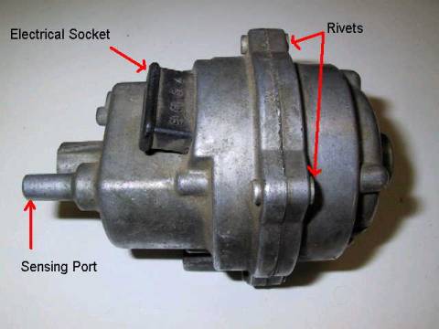
OK, if that didn't scare you off, here we go. First, a couple of pictures of the MPS:
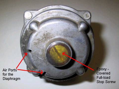
The first step in this process is to get rid of the epoxy over the full-load stop screw. Get out your hand vacuum pump and pull about 10 in. Hg of vacuum on the MPS to move the diaphragm out of contact with the full-load stop screw. This will avoid damage to the screw seals and will reduce the thermal conduction away from the screw. Take a heat gun (a real heat gun, not a hair dryer - I use a 1200 W model) and heat the epoxy to soften it. Use a small screwdriver to scrape it away from the top of the screw and the slot. Now, take a jeweler's flat-blade screwdriver and scrape the epoxy out of the exposed threads. You should scrape until you see clean aluminum and all visible epoxy is removed. Make sure the slot is absolutely clean of all epoxy. Don't worry about the position of the plug, you'll be able to position it correctly during the electronic calibration procedure.
Bosch made the screw out of nice, soft aluminum, which cracks easily. Here's how you get it out without destroying the screw. After you've removed all the exposed epoxy, start backing it out with the widest screwdriver blade you have. If you can, go to your local hardware store and find a screwdriver that fits snugly in the slot and is as wide as the slot. I use a 3/8" wide screwdriver that I filed the tip to fit tightly in the slot. I keep the mounting plate attached to the MPS and chuck it up as tight as possible in my bench vice. My suggestion is to start by tightening the screw, as there is less epoxy in the bottom threads. I often have to use a pair of vice grips on the screwdriver shank to get enough torque. Again, use your judgment! If it doesn't "break" with reasonable torque, try reheating it or spraying WD40 on the threads and waiting for it to soak in. Once you get it to break free, in a half turn or so it will jam. DON'T FORCE IT! Screw it the opposite way until it jams again. DON'T FORCE IT! Use a jeweler's screwdriver to clear out the exposed threads. Repeat this process until the plug comes out. It may take an hour or more. I strongly recommend using the heat gun to heat up the plug area each time before you turn it. It cools off rapidly and is much easier to turn when hot. In the final stages of removal, a bit of WD-40 will ease it out. Note you can also try soaking the epoxy in pure acetone to either/both soften it or remove it. I've never tried this, be careful if you do.
If you are only interested in adjusting the MPS, once you are at this point, go to the adjustment procedures below. If you want to tear into it further, rebuild it, or just see what's inside, keep on going...
Next step is to remove the rivets. I used a Dremel cut-off wheel, which worked OK - but I think the right way to do this is with a drill press. Use a fine drill right down the center and slowly work your way up in size until the rivet falls apart or can be easily drifted out.
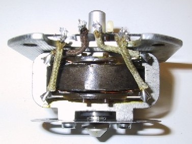
Once apart, here's the core half of the MPS:
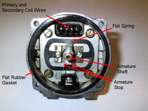
Note that in this position, the armature is fully inside of the coil, pressed there by two flat springs and a coil spring behind the assembly. This corresponds to the full-load condition. The armature stop blades retain the shaft. Removing the screws will not expose the coils, until you de-solder the coil wires to release the coils from the housing.
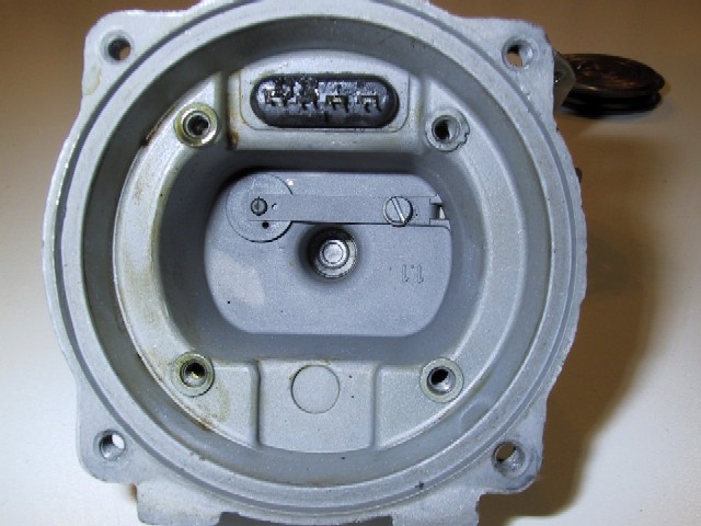
Here's the diaphragm end of the MPS:
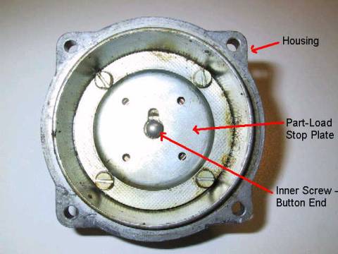
The diaphragm is behind the part-load stop plate. A gasket and a sealing ring are underneath the part-load stop plate. The button end of the inner adjusting screw pushes against the aneroid cells, with the tip of the armature pressing on the other side of the cells.
Here are the aneroid cells:
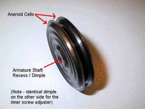
The cells seem to be welded together, and are internally evacuated. They appear to be made of bronze or copper. The rebuilt units use steel in some cases - people have complained that the steel aneroids have different expansion characteristics, but I haven't tested this. Also note the pleats on the cells that permit the cell to expand and contract. The cell's internal evacuation, diameter, shape, number and depth of the pleats, type of material (steel or brass), and thickness of the material, all contribute to the expansion characteristics of the cells.
With the plug removed, here is a view of the adjustment screws:
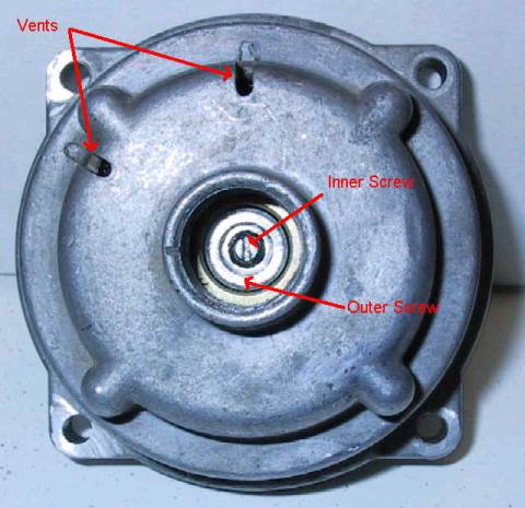
The vents expose the outer surface of the diaphragm to the atmosphere, which presses the diaphragm hard against the part-load stop plate, for intake manifold vacuum levels of more than about 4 in. Hg. The two adjustment screws can be easily seen, including the "star" hex socket of the outer screw. During adjustment, two screwdrivers are needed - one for adjustment, the second to hold the other screw in place and prevent it from turning.
Here's a look at the screws with the diaphragm removed from the housing:
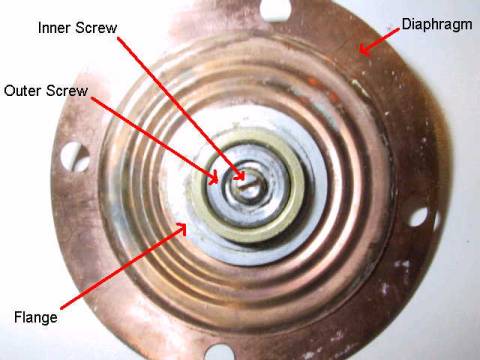
Notice also the differential pleating of the diaphragm, first described in the Theory of Operation section. The outer pleat is wider than the two inner pleats, making the diaphragm progressively stiffer as it is flexed.
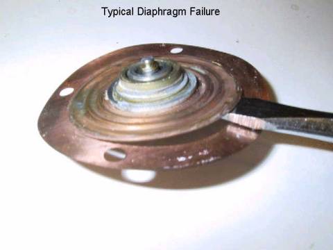
Over time, the flexing of the diaphragm under full-load operation causes fatigue cracking of the diaphragm at the edge of the flange, which makes the MPS leak. The service life of the diaphragm could have been greatly extended if Bosch had designed the clamping flange to have had a large radius edge instead of an square edge. Below is a photo of the typical diaphragm failure. Units with this type of problem must be rebuilt:
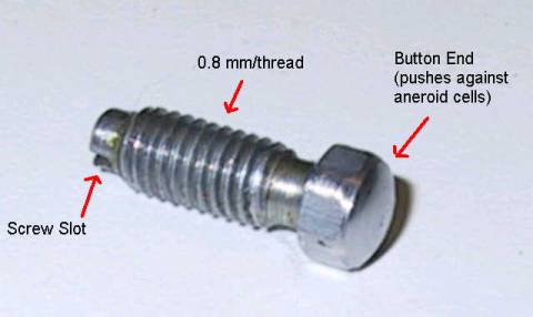
Let's move on to the screw adjusters. Here is a photo of the inner screw:
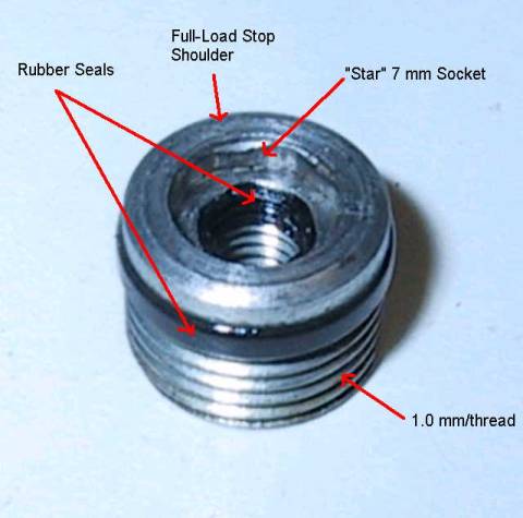
Here is a photo of the outer adjustment screw:
Below is a photograph that shows the extent of movement of the diaphragm under full-load conditions. The tool is pressing on the inner screw, and you can see that the outer screw has been pushed away from the part-load plate:
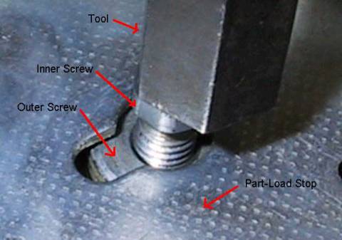
Measurements on Bosch factory-adjusted MPS's used on 2.0L 914's show this movement to be about 1.3 mm.
OK, that covers the diaphragm end pretty comprehensively. Let's look at the aneroid cells a bit more. I built a vacuum chamber out of a Clausen pickle jar with a fitting on the lid that let me pull up to 25 in. Hg or more of vacuum. I placed a graduated scale and platform inside the jar to measure the movement of the aneroid cells as a function of vacuum or positive pressure.
Here are two photographs that show the extent of movement from 0 to 15 in. Hg of vacuum:
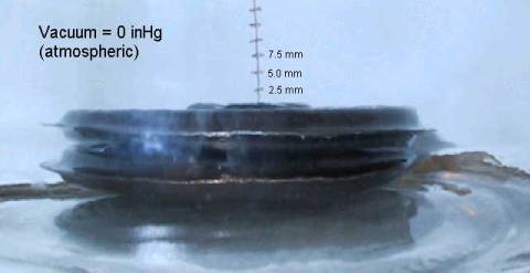
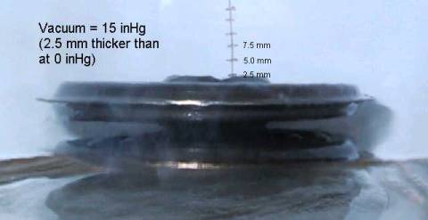
This represents the typical load range from idle conditions to wide-open throttle (WOT), or full-load. Using the expanded state as the reference level (the reason for this will be clear when we compare this data to electrically derived data in the Electronic Characterization section), we can calculate an expansion coefficient of -2.5 mm / 15 in. Hg = -0.17 mm/in. Hg.
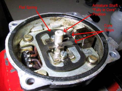
The next part of the MPS to examine is the core half of the unit. Below are two photos that show the full extent of movement of the armature.
Shaft fully in the core (labels are hard to read, from L to R - "Flat Spring", "Armature Shaft 'Fully in Core' Position", "Core Stops"):
Shaft pushed out of the core:
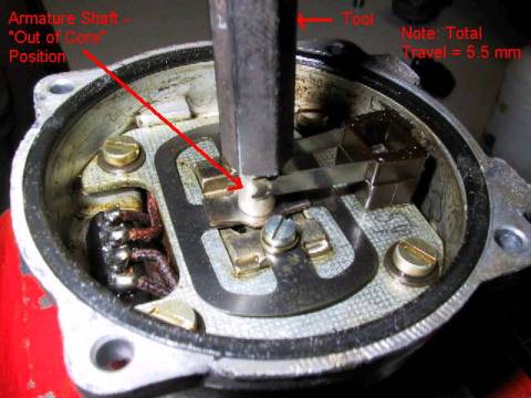
Note that for a stock MPS, the full range of motion (5.5 mm) is not covered in normal operation. The total movement of the aneroid cells plus the diaphragm over all load conditions, including overrun, is about 4.0 to 4.5 mm. As the armature is depressed, it moves out of the coil core, decreasing the inductive coupling and reducing the injector pulse width.
To remove the core, it is necessary to de-solder the coil connections and remove the four screws holding the core in the MPS body. Below is a photograph of the core assembly:
Note that there is an additional flat spring that is at the back of the core unit. The armature can be removed from the core body, but requires very careful realignment upon reassembly to make sure there is no interference. Examination of the core shows that there are only two coils, showing that the MPS is a Linear Variable Transformer (LVT), and not a Linear Variable Differential Transformer (LVDT). LVDT's can measure positive or negative displacement from a null position, LVT's only measure positive displacement.
Below is a photo of the MPS body with the core removed:
The input port is covered by a round plate with a small opening that is retained by a leaf spring. This flap valve serves a important purpose in the MPS. The MPS is extremely responsive to rapid changes in manifold pressure, even at a millisecond level. The small hole is a metering opening, designed to dampen small, rapid fluctuations in the manifold pressure from changing the average pressure level sensed by the MPS. These fluctuations in manifold pressure arise from valve timing and overlap. Without this dampening, at stable throttle position and engine load, the injection pulse duration would vary significantly, leading to roughness and higher emissions.
When the throttle is significantly opened, causing the manifold pressure to increase, the flow of air from the manifold into the MPS pushes on the plate and bends the leaf spring, opening the valve, enabling the MPS rapidly tracks the throttle input. When the throttle is significantly closed, or snapped shut, and the MPS chamber pressure is higher than the manifold pressure, the metering opening in the flap slows the flow of air back from the MPS chamber into the manifold, smoothing the MPS response.
Below is a picture of the coil spring and positioning plug:
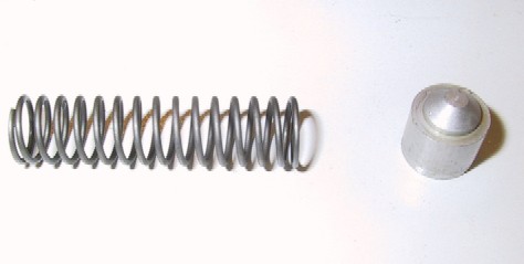
The coil spring is placed in the MPS body and the plug placed on top, where it pushes on the back of the armature. Some early versions of the MPS incorporate a spring that fits inside of this coil spring that is mounted to the body of the MPS. The spring squeezes against a prong that extends from the bottom of the armature. The intent was to provide damping to eliminate the MPS from responding to small fluctuations in the manifold pressure, as discussed above. In production MPS's, the throttle flap shown above was used instead, and the damping spring and prong were eliminated.
There were at least two different types of coil springs used. Some MPS's used a longer spring (and has a longer "nose" on the casing) than "short nose" versions.. The varying spring constant results in a different onset pressure level where the full-load diaphragm begins to move. From the very limited set of data I have, the onset vacuum level of the "long nose" units is about 8 in. Hg, and the onset vacuum level of the "short nose" units is about 6 in. Hg. Note that the rebuilders often swapped the diaphragm end of the casing with other coil units - not always with the right coil spring. I've seen rebuilt 0 280 100 037 units with both short and long nose versions.
Reassemble the two halves of the unit by tapping the core half flange rivet holes and inserting screws to replace the rivets. Note that the flat rubber seal is old and has probably lost some resiliency. The rebuilder uses a thin cross-section O-ring around the diaphragm flange to improve sealing.
We now discuss the adjustment of the inner and outer screws, full-load stop, and the effects on part-load and full-load operation. We'll start with a model MPS that is properly adjusted for part-load and full-load operation. "Tighten" = clockwise, "Loosen" = counterclockwise.
Inner Screw
If we tighten the inner screw independently of the outer screw (meaning we don't allow the outer screw to turn with respect to the body of the MPS as we turn the inner screw), the armature is driven out of the coil, reducing the inductive coupling, causing the ECU to shorten the injection pulse. This adjustment will make the mixture leaner across both part-load and full-load, because the inner screw is directly coupled to the full-load diaphragm. Similarly, loosening the inner screw independently of the outer screw moves the armature into the coil, lengthening the pulse, and enriching the mixture across both part and full-load.
Outer Screw
Under part-load conditions, the bottom of the outer screw is held against the part-load stop by the pressure differential across the diaphragm. If we tighten the outer screw independently of the inner screw (meaning we prevent the inner screw from turning with respect to the body of the MPS), the middle of the diaphragm is moved away from the part-load stop, decreasing its throw, and decreasing the amount of enrichment under full-load operation. Additionally, tightening the outer screw independently of the inner screw has the same effect on part-load operation as loosening the inner screw, enriching the part-load mixture.
Similarly, loosening the outer screw independently of the inner screw moves the diaphragm towards the part-load stop (note: in the condition I'm describing here, the MPS is under part-load pressure, and the bottom of the outer screw is in contact with the part-load stop plate), increasing the throw of the diaphragm, resulting in a larger degree of enrichment under full-load operation. Also, the effect on the inner screw is the same as if it were tightened, leaning out the part-load mixture.
However, if the outer and inner screws are "coupled" and the inner screw is turned the same amount as the outer screw, then the part-load mixture adjustment is unaffected, and the effect on the full-load mixture is the same as described above. This behavior will be exploited in describing how to properly adjust the MPS.
Full-Load Stop
The full-load stop adjusts the maximum movement of the diaphragm. Once the diaphragm engages the full-load stop, if the pressure increases further in the MPS, the mixture will continue to be richened, but at a rate determined by the expansion of the aneroid cells and not by the movement of the full-load diaphragm. Note that if the full-load stop is adjusted so that it does not make contact with the diaphragm under full-load conditions, the diaphragm will be unsupported. This over-stresses the diaphragm near the flange and leads to early failure. Most MPS's are adjusted so that the pressure level where the full-load stop is engaged is about 2 in. Hg below atmospheric pressure, though I have seen some that were adjusted to 4 in. Hg. Note that at high engine speeds, due to the pumping restrictions of the intake, even with wide-open-throttle the intake manifold is about 1 in. Hg below atmospheric pressure.
Coil Spring
While this is not an adjustment that can be made on a specific MPS, the spring constant of the coil spring sets the pressure level where the onset of movement of the diaphragm begins (Po). Bosch employed at least two different types of coil springs in the MPS's used with 914 applications that gave different values of p'. Units with the different coil springs can be identified by "short" and "long" coil spring holders in the main casting of the MPS. As mentioned above, the "short" coil spring units have a p' of about 6 in. Hg, and the "long" units have a p' of about 8 in. Hg (based on a very limited sample).
Adjustment effects are summarized in the table below:
| Adjuster | Adjustment | Part-Load Mixture | Full-Load Mixture |
| Inner Screw Alone | Tighten | Leaner | Leaner |
| Loosen | Richer | Richer | |
| Inner & Outer Screw Together | Tighten | No effect | Leaner |
| Loosen | No effect | Richer | |
| Full-Load Stop | Tighten | No effect | Leaner |
| Loosen | No effect | Richer |
To develop an electronic calibration method, readings on NOS Bosch MPS's are needed to build a set of calibration values. Unfortunately, MPS's are expensive and I have only had a few people (big thanks to: Jeff Bowlsby, Travis Neff-Hoehne, Gary Helbig, and Bill Kohne) send me units that are in good enough condition to use as calibration standards. The data below is based on a very limited sample of MPS's and will be refined as I am able to collect data on more units.
The electronic calibration method is fairly simple. Because the slope of the part-load characteristic is highly constant and not a settable parameter, the calibration can be simplified to a single setting at part-load vacuum, a single setting at a transitional vacuum after the full-load diaphragm is in operation, and a positioning of the full-load stop at atmospheric pressure.
Materials Needed
- Small flat-blade screwdrivers
- Amprobe LCR55A (the Wavetek LCR55 meter originally used is NLA) NOTE: due to the sensitive nature of impedance measurements, I cannot assure that the calibration data presented here will be accurate if a different LCR meter is used for the calibration.
- Hand vacuum pump with gauge
- Epoxy or some type of removable glue (e.g. glue gun)
|
Bosch p/n |
0 280 100 027 | 0 280 100 037 | 0 280 100 043 | 0 280 100 049 |
|
Application |
Not sure | 1973 2.0L 914 | 1974-1976 2.0L 914 | 1970-1973 1.7L 914 |
|
Sampling |
based on 1 good OEM non-rebuilt unit | based on 1 rebuilt unit | based on 2 rebuilt and 1 good OEM non-rebuilt units | based on 1 NOS unit |
| Vacuum Level | ||||
| 0 in. Hg | 1.32 H | 1.44 H | 1.39 H | 1.34 H |
| 4 in. Hg | 1.17 H | 1.26 H | 1.18 H | 1.15 H |
| 15 in. Hg | 0.72 H | 0.72 H | 0.71 H | 0.71 H |
NOTE: The values above are a function of altitude. You will need to correct these data if you are at a different altitude than my house, which is at 1,280 feet. In the future. The simplest way to calculate a correction factor is to compare the absolute pressure of your location in Torr to my absolute pressure, 726 Torr. For example:
Sea level: absolute pressure is 760 Torr. Therefore, the correction factor is 760/723 = 1.05 . So, for a 0 280 100 043 MPS, the 0, 4, and 15 in. Hg calibration values would be, 1.45, 1.24, and 0.75 H, respectively.
You can figure out your average absolute pressure by asking Google
what is the average absolute pressure at your altitude.
Demick Boyden ( on 6/2/03) pointed out to me that the method use for
correction (ratio-based) is not as accurate as determining an offset from the
slope of the part load region. The differences are small, however, on the order
of 0.01H, so it may not be significant. To use his method, you need to multiply
the part-load slope by the pressure differential (in. Hg units) between the
calibration altitude and your altitude. For the example above of the 0 280 100
043 MPS to correct for sea level, the difference in pressure between my altitude
and sea level is 723-760 = - 37 Torr = - 1.45 in. Hg. From the above chart of
MPS Inductance vs. Vacuum (for a 0 280 100 043 MPS), the slope is - 0.036 H /
in. Hg. Therefore, the offset is - 0.036 * -1.45 = 0.052 H. Adding this offset
to the readings from my calibration table results in 0, 4, and 15 in. Hg values
of 1.44H, 1.23H, and 0.76H, respectively. Note that these values differ only by
0.01H from my ratio-based approach. Unfortunately, you need the slope value to
do this method, and I only currently have the value for the 0 280 100 043 in
this page. I'll go back through my measurements and extract slopes for the other
MPS's listed above when I get an opportunity. Thanks again to Demick for
pointing out this issue. The D-Jet system has been viewed as being limited in supporting performance
modifications, but with some clever work, many modifications can be properly
tuned with a D-Jet system. Most of the modifications involve the MPS, so here
are some ideas on how to do some performance tuning. The basic need here is for more enrichment across the load range. Using an
A/F meter, the inner screw can be adjusted as described above to correctly set
the mixture. Note that the setting of the full-load stop needs to be increased
proportionally to provide proper full-load mixture after resetting the inner
screw. Other solutions
include increasing fuel pressure (up to a maximum of 34 to 35 psig), or adding
additional ballast resistance to the head temperature sensor. Again, a road test
can be used to verify proper operation by analysis of the spark plug appearance.
The maximum displacement that can likely be supported by D-Jet is between 2.2
and 2.4L. Beyond 2.4L, the injector flow rates are insufficient, even at
elevated fuel pressure. It may be possible to fit larger D-Jet injectors from
other cars (e.g. MB 450 SE). Additionally, the limits of increased ballast
resistance that can be added to the head temperature circuit are unknown. These types of modifications improve the pumping or volumetric efficiency of the engine and
generally will cause the engine to run lean, as more air is getting to the
cylinder than the MPS is calibrated for. The solution here is again to use the
part-load tuning process above. This is likely to be a superior solution over
increasing fuel pressure or modifying ballast resistance, as the effect of
increased flow in the intake system is more pronounced at high revs, and is not
linear. I used to have a section in here
on turbocharging, but I've changed my mind - don't try to turbocharge a stock
D-Jet setup, unless you're willing to do some major kludging with a rising-rate
fuel pressure regulator (RRFPR) and a vacuum switch to activate the cold-start
valve for
full-load enrichment. The problem is that when you take a look at the full range
of part-load and full-load operation, for interesting boost levels (e.g. 8 psig
and above), the MPS armature movement is insufficient. You can probably get it
to work for about 4 to 6 psig of boost by readjusting the MPS inner screw, and
by providing a reference pressure to the full-load diaphragm vent chamber, but
that's a pretty small amount of boost for all the effort it will require. Jeff
Shyu on Rennlist has built a D-Jet turbo, and he runs pretty high boost levels,
but he is using a RRFPR and a vacuum-driven cold-start valve switch, with some really
ambitious fuel pressure levels - but the jury's still out on how long this will
hold together. I'd suggest if you want to turbo your 914 that you use carbs or
an aftermarket FI system that can accommodate reasonable boost
levels. To facilitate characterization and calibration of the MPS,
a method of monitoring the effect of the MPS on the injector pulse duration as a
function of vacuum is desired. One way to do this would be to monitor the
injector pulse width directly, either through some type of in-car measurement
system, or through the construction of a bench top model of the D-Jetronic
system. Both of these approaches are possible, but require fairly complex and
expensive setups (e.g. 2nd set of FI components, special circuitry, portable
oscilloscope or pulse width meter for monitoring, etc.). Measuring pulse width
to calibrate the MPS also introduces additional uncertainties, due to the need
for the complete FI system or a bench equivalent. A simple way to electrically characterize the MPS is to
measure the inductance of either the primary or secondary coils as a function of
vacuum. Since the core of the MPS is an LVT, the inductance of either coil is a
linear function of the position of the armature in the coil. All of the Bosch
D-Jetronic MPS's have exactly the same coil windings, and show very little
variation from unit to unit, so this is a suitable approach for characterizing
the MPS. Ideally, we would like to measure the mutual inductance of the
transformer (which measures the coupling between the two coils), but this
requires specialized instrumentation and is unnecessary for our purposes. Inductance meters used to be very expensive and difficult
to come by. The availability of inexpensive multimeters has made this a
non-issue. The successor to the Wavetek LCR55 meter I used is the
Amprobe LCR55A which is considerably
more expensive at $340. I am evaluating the FNIRSI LCR1020E, which is
much cheaper at $70, and will update this document in the future on my comparison. The secondary coil of the MPS was chosen for the
characterization and calibration curves shown here, as it has a higher
inductance than the primary and produces a larger signal (usually more
accurate). Due to the large size of the core and large number of windings, the
maximum inductance values are fairly large, between 1 to 2 Henry (H). All the
measurements shown here were taken on the 20 H range of an LCR55 meter. The 2 H
range did not have sufficient drive for the quality factor of this coil and does
not produce accurate measurements. Note that cheaper DMM-based inductance
meters (like the Wavetek 27XT) lack sufficient current drive to test this large
inductance accurately and are not recommended for use in this application. Below is a typical inductance versus vacuum plot for an
MPS: Below are the primary characterization data that can be
extracted from this plot: Note that the onset of full-load at 6 in. Hg (about 150
Torr below atmospheric pressure) and the engagement of the full-load stop at 2
in. Hg (about 50 Torr below atmospheric pressure) correspond almost
exactly to the settings defined by Bosch for the operation of the full-load
diaphragm. It is interesting to note that during over-run conditions,
the mixture is slightly richer (e.g. more inductance) than required, due to the
armature being pushed out of the LVT coil. The vacuum limiter (decel) valve helps reduce the
emissions from this over-rich mixture by reducing the peak over-run vacuum and
adding additional air to the mixture to increase the air-fuel ratio. In early
D-Jetronic implementations, the ECU senses the over-run condition by monitoring
the idle contact switch and the engine speed, and inhibiting injection during
overrun to reduce emissions. However, it was later discovered that cooling of
the cylinder walls during fuel shut-off caused enhanced hydrocarbon emissions
when the throttle was opened again and fuel delivery resumed. This discovery led
to the elimination of the over-run shut-off circuit in later D-Jetronic ECU's,
and the incorporation of the vacuum limiter valve. Below are measurements taken on a disassembled core of a 0
280 100 049 MPS: Armature fully in the core:
1.83 H (up against the core stop, click link to see picture) Using a vernier caliper to measure the secondary
inductance vs. displacement on the disassembled core, the following graph is
created: Note the similarity of the inductance characteristic for
displacements over 4 mm to the inductance vs. vacuum relationship when the
vacuum level is greater than 18 in. Hg. The linear region of the inductance vs.
displacement region extends from about 1 to 4 mm, and the overall
characteristics are very similar to the general characteristics of LVT's from
the references above. The slope and intercept were extracted using least-squares
analysis of the linear region from 1 to 4 mm. From these measurements on a bare core, the non-linear
behavior in the range from 18 to 25 in. Hg is shown to be due to the armature
reaching its limit and being pressed against the core. At 0 in. Hg the core
position can be calculated by substituting the measured inductance of 1.37 H
into the linear model extracted from the data above, and equals 2.1 mm. Since
the linear region extends down to 1.0 mm, this leaves about 1.1 mm of additional
adjustability. This additional range can be exploited when richening the mixture
for engine modifications, as described in the
Performance Modifications and Tuning section of this document. Using the extracted slope of the linear region, we
can calculate the expansion coefficient of the aneroid cells from the plot data.
Taking the reciprocal of the inductance vs. displacement slope (-3.45 mm/H) and
multiplying by the inductance vs. vacuum slope, we get 0.036 H/in. Hg * 3.45
mm/H = -0.12 mm/in. Hg (the "-" sign is correct, it arises due to
the reference point I selected for measuring the core displacement). This
compares fairly well to the figure of -0.17 mm/in. Hg that was derived from the
vacuum chamber measurements of the aneroid cell expansion. The lower
electrically-derived value may be due to experimental errors, but it is likely
an actual effect due to the compressive stress on the aneroid cells from the
wave and coil springs. These results also point out that the slope of the linear
region of the plot is solely a function of the expansion coefficient of the
aneroid cells and the spring constants of the wave and coil springs - and is
therefore non-adjustable without modification to these components. Readings on all of the MPS units I've tested to date show
a total variation in part-load slope of about 10%. Based on this preliminary
data, it is reasonable to assume that all of the aneroid cells and coil/wave
springs that are in the units that I have tested (which are all physically the
same) are essentially identical within expected manufacturing tolerances. Well, after a long search, I found the Bosch US patent (#
3,583,374) for the type of MPS used in the 914, the model with the full-load
diaphragm. Go to http://uspto.gov to find and
view the patent. I spent a few hours
analyzing the patent in detail, here are the additional things I uncovered: Bosch also shows several interesting variations in the patent. Item 37b is a
schematic of another version of the MPS that depends on a second aneroid cell
for the full-load enrichment, using a very complex series of coupled movements
(took me 30 minutes of staring at it to figure out how it worked). They also
show two interesting adaptations (37E and 37F) of the part-load stop plate that
permit the MPS's part-load response to be corrected for altitude. Both
incorporate a second, perforated diaphragm that allows the part-load stop plate
position to move as the external pressure varies. Neither were ever put into
production, apparently due to cost, complexity, etc. Imagine what a nightmare
the MPS would be if there were TWO of those flaky diaphragms!! I also recently found the two Bosch patents for the early pressure sensors
that lacked the full-load diaphragm. Both links are on the
D-Jetronic
Fundamentals page. I also found a very interesting patent from Nippondenso
(also listed on the page) for an MPS very similar to the full-load diaphragm
Bosch MPS, but with a port for supplying the induction pressure to the reference
side of the diaphragm - exactly the solution I proposed for dealing with forced
induction. I have no idea of it this device was ever put into production, but it
would be interesting to find one and compare it to the Bosch MPS. Perhaps it has
greater range and can accommodate higher boost pressures. Like any extension of knowledge, I have depended heavily on the experience
and knowledge of others who have helped me immensely in understanding the MPS
and the D-Jetronic system in general. A special thanks goes out to Jim Thoursen
and Dave Darling, who both have spent countless hours working on their
D-Jetronic 914's and passing their knowledge on to other 914 owners, including
myself. My next special thanks are to the members of Rennlist, who represent the
largest repository of 914-specific information and knowledge in existence.
Another special thanks goes out to the folks at Pelican Parts, for providing a
great website and source for Porsche parts. And another BIG thanks to Don
Burdenhart of Bret Instruments, who spent 30 minutes on the phone with me
explaining how they do MPS adjustments and rebuilds, and who also sent me three
scrap MPS's to play with and analyze (thanks to Jeff Shyu for shipping them to
me!). Ralph Ricks sold me an MPS that I was finally able to get the last pieces
together of how the outer screw adjustment affected the characteristics. Additional thanks go to the many FAQ's and web sites where others have
published their learnings. Here is a list of a few of the individuals who have
helped me, it's incomplete, and I missed you, please forgive me!
Kjell Nelin Performance Modifications and Tuning
Increased Displacement and Compression
Throttle Body, Head Porting and Valve Size Modifications
Turbocharging
Common Questions and Answers
A: If it's the same type of MPS, is in good shape, hasn't had the epoxy
seal removed, and has the same "nose" length, it might work well
enough to get you home and get around, but it's unlikely that it will work
properly under heavy and full-load conditions. From what I can tell - and
this is an engineering conjecture - Bosch designed the D-Jetronic system so
that for a specific type of MPS (e.g. double-aneroid, full-load diaphragm,
short nose variety), the part load characteristics were identical. Take a
look at my calibration table for evidence - the setting for 15 in. Hg is
essentially the same for all of the MPS's in the table. I believe they did
this so that they could build a run of MPS's, mass-adjust them to a
part-load spec, then put them into inventory. Then, when orders came in for
a specific MPS, they'd pull the stock units, set the transition slope to a
spec, install the full-load plug and adjust to spec, stamp it with the p/n, seal it with epoxy and
ship it. What this means for us is that under light-to-medium part-load
conditions, all MPS's of a specific mechanical type will act the same. But,
as you can see from my calibration table, the transition and full-load
values vary for each application. It should be possible to re-calibrate any
MPS of a specific mechanical type to the specifications of any other MPS of
that type.
A: Some of the old D-Jet
references suggested a procedure like this to fix part-load mixture issues.
The problem with this procedure is that it doesn't comprehend that the
full-load stop (the "plug") is a critical adjustment in this system.
Removing the plug and either not replacing it or screwing it in randomly
will likely result in either a rich or lean full-load mixture, and possible
premature failure of the diaphragm due to mechanical stress. Also, depending
on the vacuum level in the MPS, turning the inner screw usually turns the
outer screw at the same time, due to friction on the threads. This causes
the part-load mixture to remain unchanged, but changes the full-load mixture. I
strongly suggest that you do not adjust the MPS without using an LCR55A to
first characterize the secondary inductance vs. vacuum characteristic.
Otherwise, you will lose your reference point for all three adjustments and
probably won't be able to get back to them by random adjustments.
A: Just about every repair technique has been attempted on cracked
diaphragm, some people have been satisfied with the results. But be aware of
the potential problems. First, you have to open the MPS, which means
carefully removing the rivets, carefully noting the orientation and order of
all the parts, and hoping and praying that the rubber flange seal will not
leak when you re-assemble the unit. The next problem is the nature of the
repair. Since it's
unlikely you have any spare OEM diaphragm blanks around, repairs are limited to layering of materials on the
diaphragm (e.g. brazing or gluing on foil layers) or soldering the crack
closed. Soldering sounds pretty good, it may actually work
OK in situations where the crack is small (2 or 3 mm), but if its a big
crack, it's likely to fail again due to the ductility of the solder.
My suggestion is to not waste your time trying to repair a cracked
diaphragm.
A: When I first heard this I thought it was BS, but I've become
convinced it may be a real problem. If you rotate your engine backwards
during a spin with the throttle plate closed, and cause the engine to
pressurize the intake manifold, the overpressure can cause a fatigued (or
possibly a new) diaphragm to crack. Bosch never designed any overpressure
protection into the system. If you anticipate this may be a problem (e.g.
you drive at the track a LOT), then you might want to rig up a low-pressure
pop-off valve that will relieve positive pressure over 2 to 3 psig in the
line to the MPS. Note that this problem also manifests itself when people
turbo their D-Jet setups, without providing a reference pressure from the
turbo to the vent side of the full-load diaphragm.
Electronic
Characterization
Armature fully out of the core: 0.56 H
(wave spring pressed up against, core, click link to see picture)
Bosch MPS Patents
Acknowledgements
Alfred Schwenk
Frank Kerfoot
John Larson
R.K Herzog
Jeff Shyu
Steve Milo
Wayne Dempsey
Travis Neff-Hoehne
Jeff Bowlsby
Gary Helbig
Bill Kohne
Ralph Ricks
Demick BoydenChanges by
Version
References